Example Pipeline
Please keep that in mind, the example you are going to proceed with is based on our R&D studio. Various aspects might differ from your setup. If you have any further questions, do not hesitate to contact our Support Department.
Preliminary Preparation
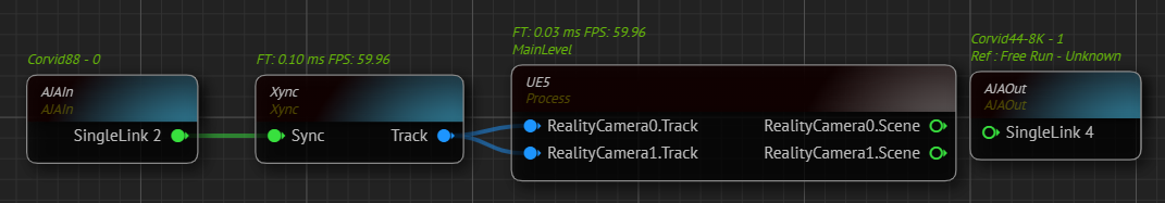
- Prepare your scene, launch it via Reality Hub Launcher module.
- Drag & drop the
UE5processing node into Nodegraph canvas. - Create two Reality Cameras. See Actor Spawning.
- Add
AJAInandAJAOutnodes, select your devices and outputs based on your setup. - Create your Track node. (In our example it will be the
XyncNode)
Modifying Curve XR Node
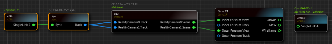
- Add
Curve XRnode to the canvas. - Change the following properties based on your measurements: Pitch Angle, Cell Width, Cell Height, Columns Count, Rows Count, Left Tilt/Roll and Right Tilt/Roll, Height Offset, Left Point and Right Point, Cell Resolution, Canvas Resolution.
- Duplicate the modified
Curve XRnode. - Connect the
RealityCamera0.Sceneoutput of theUE5node toInner Frustum Viewof theCurve XRnode. - Connect the
RealityCamera1.Sceneoutput of theUE5node toOuter Frustum Viewof theCurve XRnode.
Preparing Inner Frustum Track
- Create
Add Tracknode. - Connect the
Trackoutput ofXyncnode to theXinput of theAdd Tracknode.
To address a delay in the Inner Frustum at certain zoom levels, which causes a collision with the outer frustum, we must provide additional FOV input for tracking. Our example requires an additional 10-degree field of view (FOV).
This delay is inherent to the tracking process and rendering of the inner frustum.
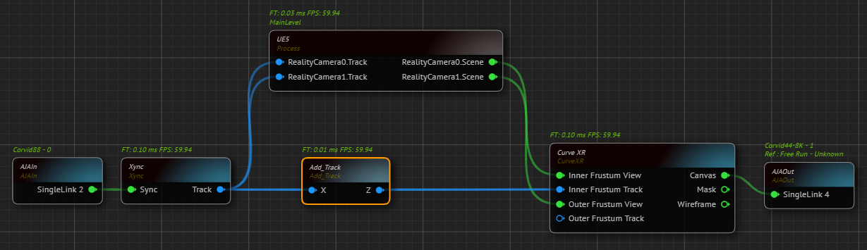
- Expand the
Yproperty and change theFOVproperty to 10. - Connect the
Zoutput of theAdd Tracknode intoInner Frustum Trackinput pin of theCurve XRnode.
Pan, tilt, and roll can now be performed independent of zoom level without causing collisions.
Preparing Outer Frustum Track
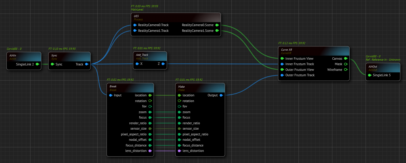
- Create a
Breaknode. - Connect the
Trackoutput ofXyncnode intoBreaknode'sInputpin. Now we have access to Track data. For more details, see Dynamic Nodes. - Create a
Make Tracknode. - Connect every
Break Tracknode’s output to the matching inputs of theMake Tracknode, except forRotationandfovpins.
Inner Frustum rendered based on where the camera is looking and what is its resolution. On the other hand, the Outer Frustum render continues even if the camera is looking towards a different direction than the LED Screen, because the main purpose of it is to illuminate the scene and talent.
No matter what zoom level you are in, Outer Frustum must always encompass the LED screen, therefore Outer Frustum’s FOV must be fixed.
In the following steps, you need to get the Rotation and FOV data from your Track while framing the LED screen with your studio camera and keeping the zoom level zero, but the driver still will be the Inner Frustum, the first Track Node we added.
Now:
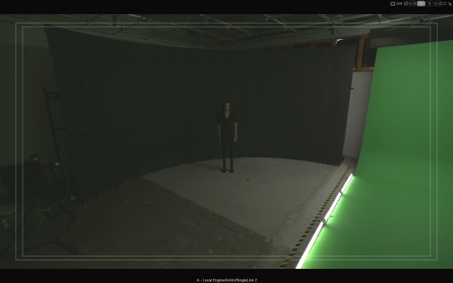
- Frame the LED screen with your studio camera and keep the zoom level at zero, as illustrated above.
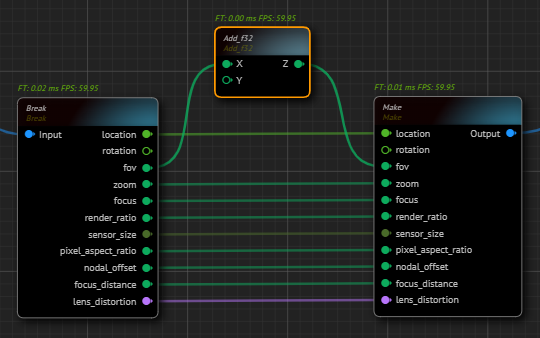
- Create an
Add f32node. - Connect the
fovoutput of theBreaknode into theXinput of theAdd f32node. - Connect the
Zoutput of theAdd f32node to thefovinput of theMake Tracknode.
Now we have the FOV value in the full zoom out while our camera is framing the LED screen. On the other hand, the driver still will be the Inner Frustum. Therefore, we need to disconnect the X output of the Add f32 node from the fov.
- Disconnect the
fovoutput of theBreaknode from theXinput of theAdd f32node.

As the above image suggests, Outer Frustum is rendering with 97 FOV. We need to increase the FOV X and Y by 30 degrees to compensate. With this change, Outer Frustum will project the image onto LED screen with 127 degrees to encompass the LED screen.
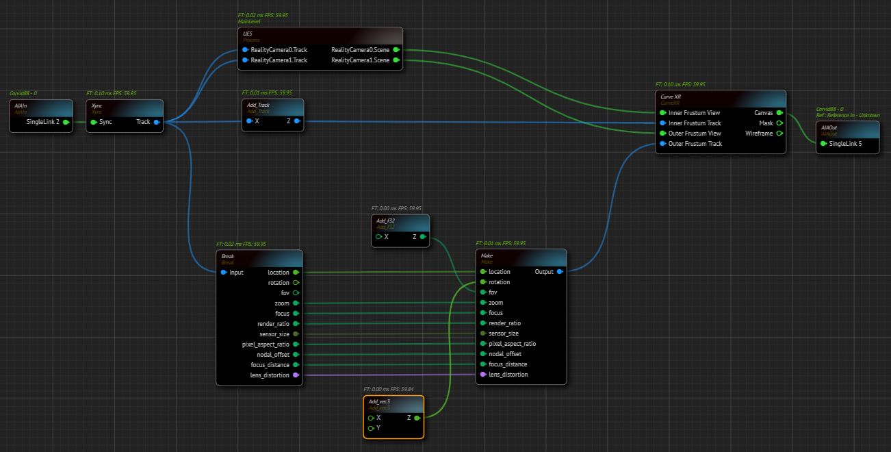
- Create an
Add vec3node and connect itsZoutput toRotationinput of theMake Tracknode. - Connect the
rotationoutput pin of theBreak TracktoXinput of theBreaknode. - Disconnect the
Zoutput of theAdd vec3node to thefovinput of theMake Tracknode. - Connect the
Canvasoutput of theCurve XRnode toAJAOut, as illustrated above.
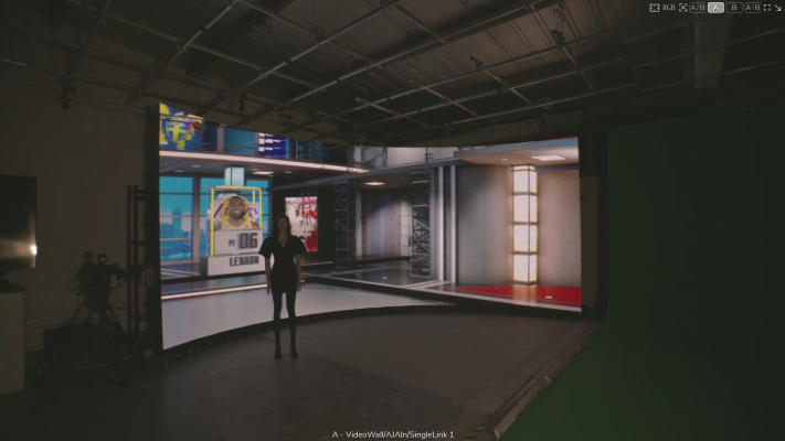
Our scene is successfully projected on the Curved LED.