Operating Gang Mode
![]()
The following example contains three different Engines, as shown in the image above. All three Engines have the following setup in common:
- Engines are launched with the same Unreal Project (*.uproject)
- Engines are running in Configuration Mode
- Engines have no RGraph
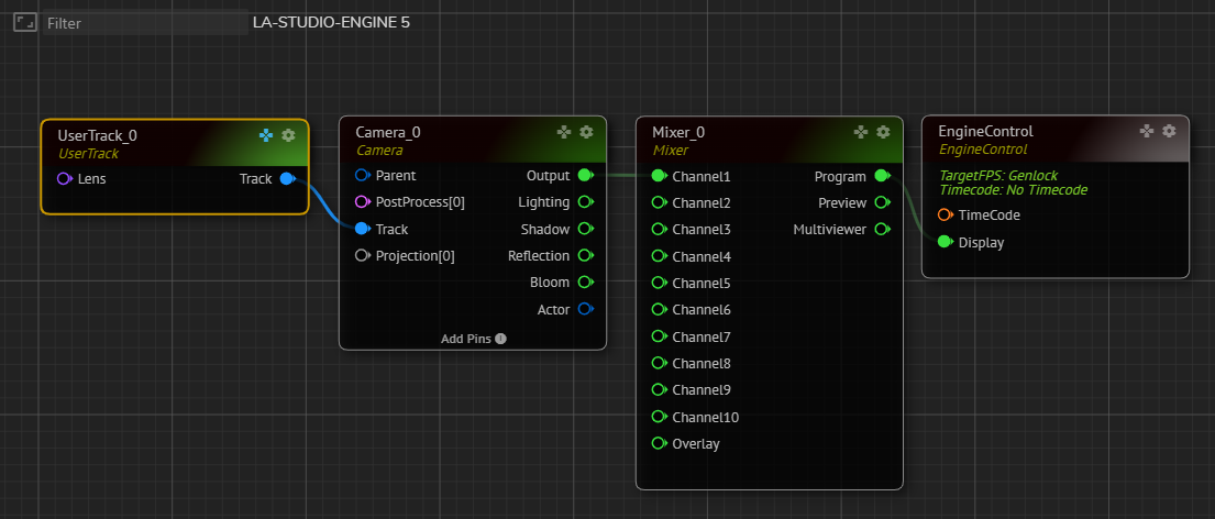
Create the node tree as shown on the image above by following connections:
EngineControlnode’sDisplayinput pin toMixer_0node’sProgramoutput pinMixer_0node’sChannel1input pin toCamera_0node’sOutputpinCamera_0node’sTrackinput pin toUserTrack_0node’sTrackpin
The node tree is ready.
Now:
- Select the node tree except for the
EngineControlby clicking and holding your left mouse button and dragging over theUserTrack_0,Camera_0, andMixer_0nodes - Copy the node tree you selected by pressing CTRL + C on your keyboard
- Go to the Engine Toolbar, choose Engine02
- Paste the node tree you copied earlier into Engine02’s Nodegraph by clicking CTRL + V on your keyboard
- Connect the
Mixer_0node’sProgramoutput pin toDisplayinput of theEngineControlnode inside the Engine02 - Go to the Engine Toolbar, select Engine03
- Paste the node tree you copied earlier into Engine03’s Nodegraph by clicking CTRL + V on your keyboard
- Connect the
Mixer_0node’sProgramoutput pin toDisplayinput of theEngineControlnode inside the Engine03
info
Please remember that Gang Mode is a Nodegraph operation requiring identical Node types with the same name.
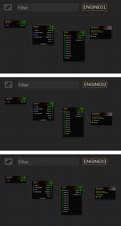
All three Engines have the same RGraph construction, as shown in the image above.
Now:
![]()
- Activate the Gang Mode you learned in the earlier section
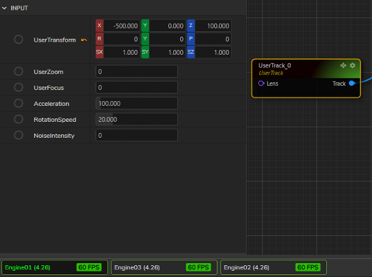
- Select the
UserTrack_0node located inside the Engine01 - Go to
Inputproperties of theUserTrack_0 - Change the
User TransformXvalue from -500 to -400
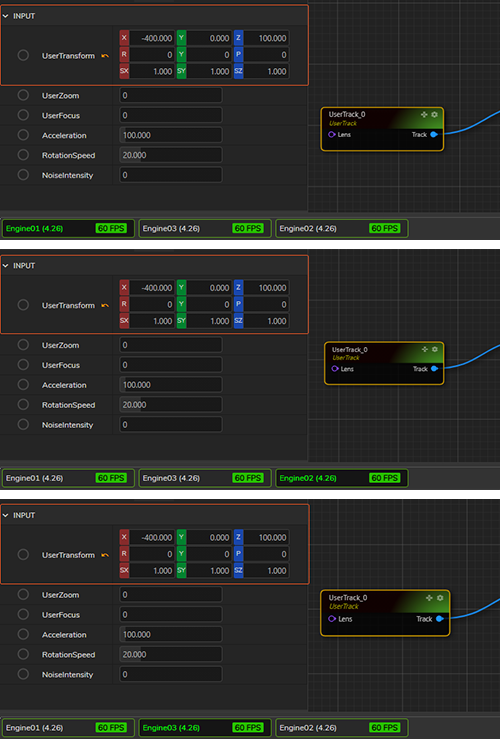
Since all three Engines are included in the Gang Mode, the change you made in the User Transform X value is reflected in the Nodegraph of the Engine01 and the Engine03, as shown in the image above.