Lens Calibration
Reality has to know the following values of the lens, in order to render a frame:
- Field of View
- K1 and K2 radial distortion coefficients
- Nodal offset (some tracking devices add this value to its tracking data)
- Focal depth (so far, no tracking device provides this data directly)
- Center shift
Some tracking devices provide some the lens information above, some only send raw zoom and focus encoder data. We will go into the details of many tracking devices while explaining each different type of tracking node.
Lens Calibration Files
In case we would like to handle all lens calibration within Reality using zoom and focus axis data, we have to define our lens files using Reality Editor. There are some sample lens calibrations placed under …\Zero Density\Reality\4.27\Engine\Plugins\RealityEngine\Content\Lenses folder.

Creating a lens calibration requires special training from Zero Density.
Usually the lens calibration files are a basic match between different serial numbers of the same lens make and model. Your serial number of the same lens might not be close enough to the lens we calibrated. If you require very precise tracking, your “camera+lens” combo has to be calibrated specifically for the best results.
Field of View
The FOV values are defined as horizontal field of view in degrees. Reality calculates the vertical field of view, depending on the aspect ratio of the camera sensor calculated using SENSOR WIDTH and SENSOR HEIGHT values.
Radial Lens Distortion
Reality Processing Engine uses the following lens distortion model:
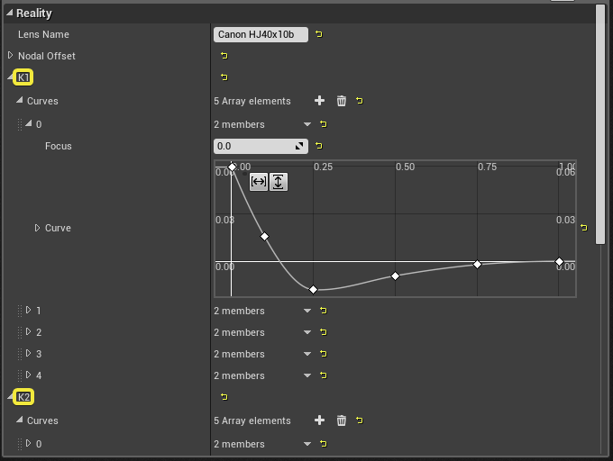
The radial lens distortion is made from the center, every pixel’s distance from the center is assigned to 𝑟 and a new 𝑟′ is calculated using 𝑘₁ and 𝑘₂ coefficients. These coefficients usually change at every zoom (on some lenses also focus) level of a zoom lens. Tracking devices providing also lens calibration, send the distortion coefficients at every frame according to the lens zoom and focus axis. The zoom and focus axis data is mapped to a curve and the LENS node interpolates the curves and provides these values to the tracking node.

Nodal Offset

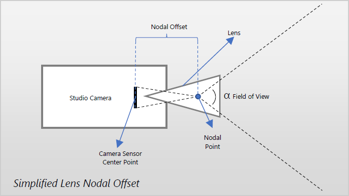
The above drawing shows a simplified explanation for lens nodal offset. This point is also mentioned as: “entrance pupil” or “no parallax” point.
The nodal point will change over the zoom and focus range of the lens. So, this offset is defined with curves for different zoom and focus levels during lens calibrations.
Reality CAMERA nodes render looking from the “Nodal Point” in 3D space. If the tracking device or lens calibration file doesn’t offset the nodal point correctly, the tracking will not be accurate.
Usually tracking devices that don’t supply their own lens calibration, will send the “Camera Sensor Center Point”.
Focal Distance and Depth of Field
Tracking devices that send “Camera Sensor Center Point” and lens focus encoder data can be used to focus pull graphics rendering. This parameter is expected in centimeters and the resulting depth is passed to the FOCAL DISTANCE parameter of POSTPROCESS node.

By default, “CircleDOF” method is used for simulating focal depth, which can match to the physical camera lens, better than the other options. The FSTOP parameter is set to “4.0” by default and it is simulating the “iris” of a physical camera lens. If we increase “F-stop” value, the “lens blur effect” will diminish. To increase the lens blur effect, you have to lower this value.