Augmented Reality Virtual Studio
In this section, we will be utilizing Reality Hub’s ready-to-use Composite Augmented Shadow template.
- Go to the Reality Hub, and activate the Nodegraph/Actions tab,
- Click on the Nodegraph Menu
- Go to Load Template and select the Composite Augmented Shadow
The SDI Inputs and Outputs
After making sure that AJA card/s is properly installed, driver updated and firmware checked, you should manage the values on AJAcard and AJAin.
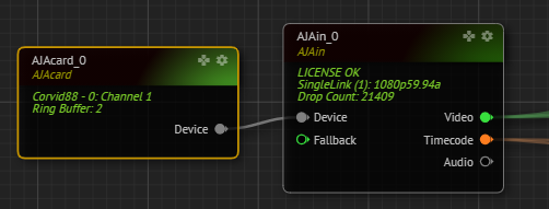
Please make sure the DeviceID is selected on AJAcard.
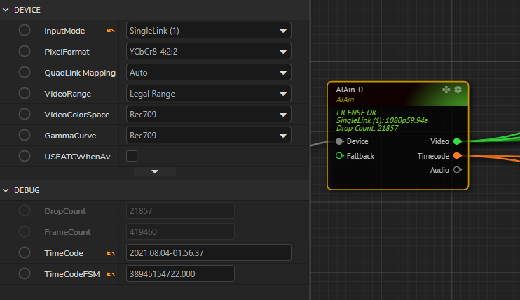
Choose the InputMode the same as the input pin on the physical AJAcard, in this example, it will be SingleLink (1) as an HD Input:
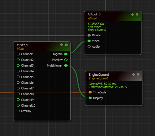
Now go to the AJAout and see that the Program pin of Mixer node is connected to the Video pin of the AJAout node.
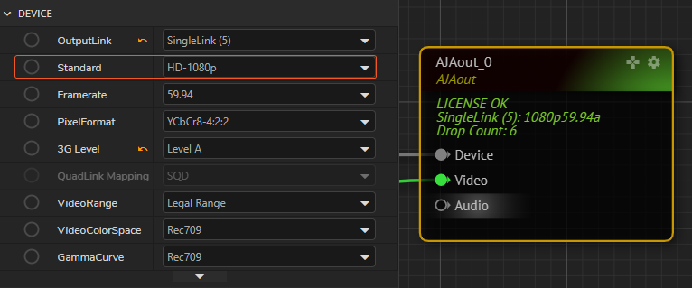
Choose the OutputLink the same as the input pin on the physical AJAcard, in this example, it will be SingleLink (5) as an HD Output:
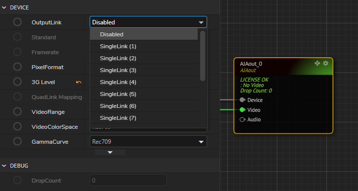
And it is very important to choose the right Video Format (Standard) to be able to see the display on your SDI Output, otherwise, you will either see a distorted image or no image at all on your display monitor.
Lens and Tracking
Lens and tracking nodes provide the visualization and configuration of the physical lens on the camera and the tracking system installed in the studio. By default the lens and tracking related nodes are as below:

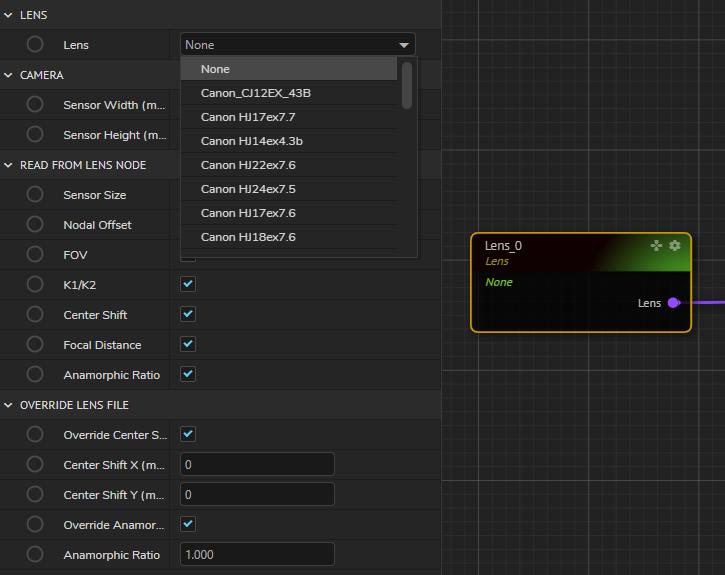
Choose the right lens on your system, if you think that your lens is not yet on this list, please choose the closest one that applies and in this case please consult to Zero Density Support Team for any inquiries for deciding the correct lens.
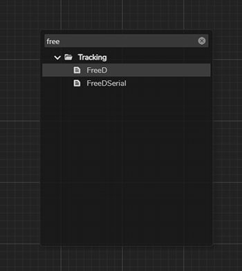
By default, the UserTrack node is on the templates and you can choose and modify the tracking parameters by adding a FreeD node to your Reality Hub nodegraph to see the available tracking devices on Reality and note that Reality is compatible with any tracking device that is using FreeD protocol which can be activated through FreeD nodes.
Once you add the right tracking node, go to Device properties and make sure that:
Enable Deviceis set toTrue.UDPPortorPortNameis correct which is configurable on this property according to the physical device'sUDPPortor thePortNameon the engine.Protocolis correctly set to D1 or A1 which should be consulted to your tracking solution provider.
After finishing the configuration of Lens and Tracking nodes, you should be seeing the data flowing from the tracking device. Please make the necessary check if the data flow is correct and fine-tuned.
Projection
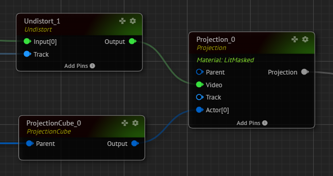
In Reality, talent is composited with graphics in a 3D scene, rather than layer-based compositing. This is provided by projecting the talent on a mesh called Projection Cube. Projection node requires an undistorted image of the SDI Input. Thus, we add an Undistort node before connecting the SDI Input to Video pin of the Projection node as shown below:
Modify the Reality Geometry of the Projection Cube so that it fits the scene and the physical studio which are by default as shown below:
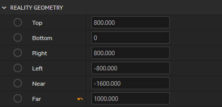
You can enter the below values which correspond to 50 meters to the right, left, near, and far from the zero points of the set if you have not changed the Transform of the Projection Cube. The values below correspond to 100*100 meters (shown in centimeters) projection area which will be big enough for your needs within your production.

Post Process
There are many capabilities of Post Processing powered by Unreal Engine. In this tutorial, we will cover how to create shadows of virtual objects:
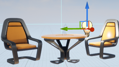
Go back to Reality Editor and add a Point Light Asset to your set on a position near to chair and see that it is listed on the World Outliner on the right side of Reality Editor.
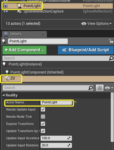
Add ZDActor to this asset by clicking on Add Component and rename it as PointLight to be able to view it on the nodegraph.
Go to Transform and make it Movable.
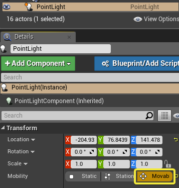
Now type ZD while clicking on PointLightComponent (Inherited) to view the ZD Shadow Channel and choose either Red, Green, Blue or Alpha. Please note that you can add up to 4 lights that will render shadow in a set by choosing different Shadow Channels.
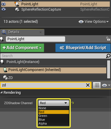
Save the Project and click on Play again and go to Reality Hub Nodegraph and click on the EngineControl node to see if RenderShadow is enabled and set to True.

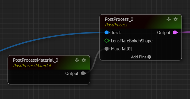
Go to PostProcessMaterial node and see if the Material is set to RealityShadowsAO

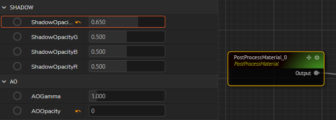
The lights are added in numerical order so the PointLight we have added is on ShadowChannel1. We can manage the Opacity of the Shadows on ShadowOpacity which is 0.500 by default and notice that the opacity of the shadows is changing.
Final Compositing
Finally, camera input, virtual objects, and post-processing parameters are all going into CompositePasses node for the final output.
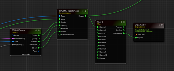
To be able to see the shadows, make sure that the Shadow pin of Camera node is connected to the Lighting pin of the CompositePasses node.