Cyclorama Setup
If you are going to produce a virtual studio program, you will need a green screen or blue screen cyclorama. Usually these cycloramas are built using 1, 2 or 3 walls. The walls should have rounded cove in the edges and corners. Cyclorama walls can be custom built or may be provided from specific manufacturers.
No matter how the cyclorama is built, the most important thing in a cyclorama is the rounded cove edges and corners. Then comes the painting and lighting of the cyclorama. Reality creates a simulation of the actual physical cyclorama in virtual world as a 3D mesh. The masks are created accordingly.
Measuring the Dimensions of the Cyclorama
Here is an example of a physical cyclorama:
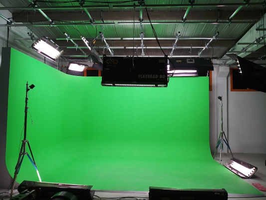
If you already have the dimensions of the Cyclorama, that would be more practical. But still, you can measure the dimensions following the steps below:
Setting Cyclorama Node to “Debug” Mode
Various nodes have a special debug mode. To toggle the debug mode for a node, click the gear icon on the right corner. If the debug mode is active, it will be drawn as orange.
Before going on-air, you should disable the debug option.
For more details, visit the Node Structure section on the Reality Hub Documentation page.
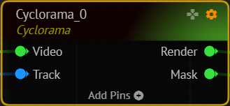
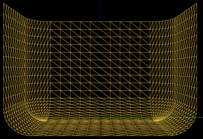
When the node is set to debug mode, instead of rendering the synthetic clean plate, it will draw the cyclorama as a 3d wireframe mesh. This mode is particularly useful during the cyclorama setup.
Now go to Delay node and connect the Output pin of the Delay node to Channel1 of Mixer node. Then connect the distorted image of the Render pin of the Cyclorama node to the Overlay pin of the Mixer as shown below:

Depending on your studio's zero point and the camera transform, the cyclorama might be observed as shown below (If the zero point of the set is visible by the current camera input):
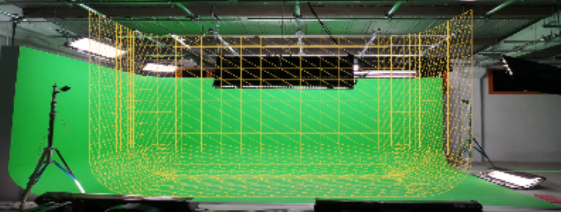
This cyclorama is drawn by default values. Let's start adding real values of our own cyclorama.
Height of the Cyclorama: Z dimension
The height of the cyclorama should be measured from the top point of the cyclorama to the lowest point as shown in the photo below:
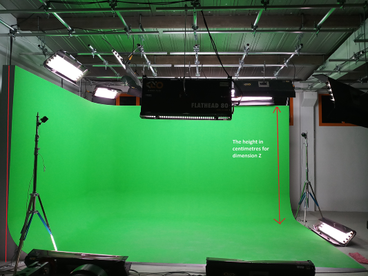
The height of this cyclorama is 300 cm. And this value will be entered into the Z value of the Size property of the Cyclorama node.
Width of the Cyclorama: Y Dimension
The width of the cyclorama should be measured from the most left point of the cyclorama to the rightest point as shown in the photo below:
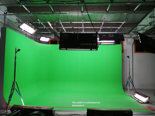
The width of this cyclorama is 477 cms. And this value will be entered into the Y value of the Size property of the Cyclorama node.
Depth of the Cyclorama: The Wings
In real-life applications, some of the customers would want to have a cyclorama with different wing lengths. Thus, the depth of the cyclorama might vary on both sides thus you can enter these values separately. Please remember that the wing lengths should be measured from the ending point of the curve to the end of the cyclorama.
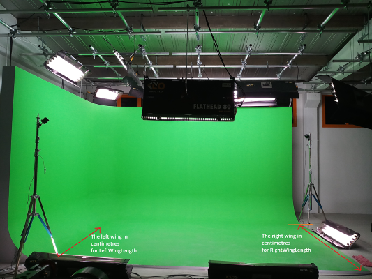
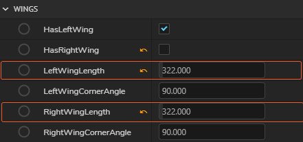
Before entering the values. we see that there is a left wing of this cyclorama but there is no right wing. Thus, we uncheck the HasRightWings checkbox shown below:
Here in this example, both wing lenghts are the same and it is 322 cms. These values will be entered to the Wings value of the Cyclorama node.
Vertical Radius
In a cyclorama, you also have a cove and this cove radius has to be entered to property.
Measuring the Transform Values of Origin of the Cyclorama
Setting Origin: The “0” point
You have to set the origin in your physical set, and mark it. This is needed for setting up your tracking cameras relative to your origin. Think of a tracked tripod head, you have to measure where your tripod is located relative to your origin. Whenever you move your tripod, measuring the X, Y, Z coordinates relative to the origin will become necessary.
Preset Origin Locations
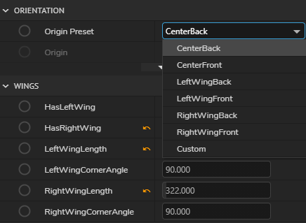
By default, the Origin Preset property is set to “CenterBack”, which means the center of the middle wall on the ground. But you can choose different preset values or you can enter a “Custom” coordinate relative to “CenterBack”.
If you want to see where the “Origin” is located, you can set DrawAxisMarker to “True”.
Setting Transform Values after Measurement
In this example, zero point of the set is on the right front of the cyclorama which has been previously arranged during Tracking Calibration. Thus we will measure the distance of the origin to this point in each dimension as shown below:
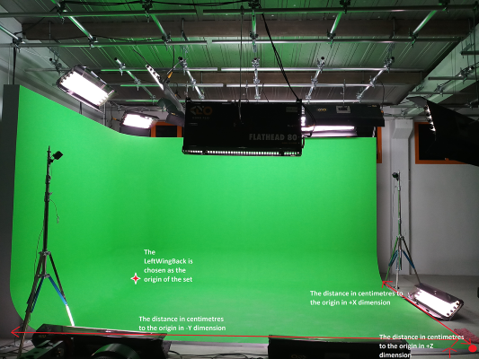
And enter these values accordingly:
XProperty: The distance of the origin in X dimension in centimetresYProperty: The distance of the origin in Y dimension in centimetresZProperty: The distance of the origin in Z dimension in centimetres
Mapping “Clean Plates” onto Cyclorama
After we made sure that we have an accurate representation of the physical cyclorama and tracking, we can capture clean plates of our cyclorama and map on to our geometry. This way, RealityKeyer node will be able to get the necessary “Clean Plate”. Just make sure that Cyclorama node is not in “debug” mode. This way the node renders the mapped images on the cyclorama mesh.
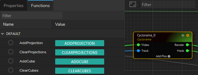
To capture clean plates, first clear the previous captures with ClearProjections button, then go as wide as you can with your tracked camera and click on AddProjection button. Since it might not be possible to capture all of the cyclorama with single projection, you might need to repeat the above process until you cover all of your cyclorama.
Try to capture the whole cyclorama with as few captures as possible, avoid multiple captures as much as possible. It won’t help to increase the quality but it will only add additional processing load onto the Reality Processing Engine.
Adjusting “Garbage Matte” Softness

If your camera sees some areas out of your cyclorama, those areas have to be masked out. Since we defined the geometry of the cyclorama, “Reality” can actually do it automatically. The softness of this matte can be adjusted by setting Smothness property.
Smothness property is also affected by SegmentCount property.