Adding Custom Blueprint Nodes
In your projects, it is possible to create nodes specific to your needs and use them on your Reality Suite. You can access these nodes through your Reality Setup, Action Builder and Control.
Creating a Blueprint Node in Reality Editor
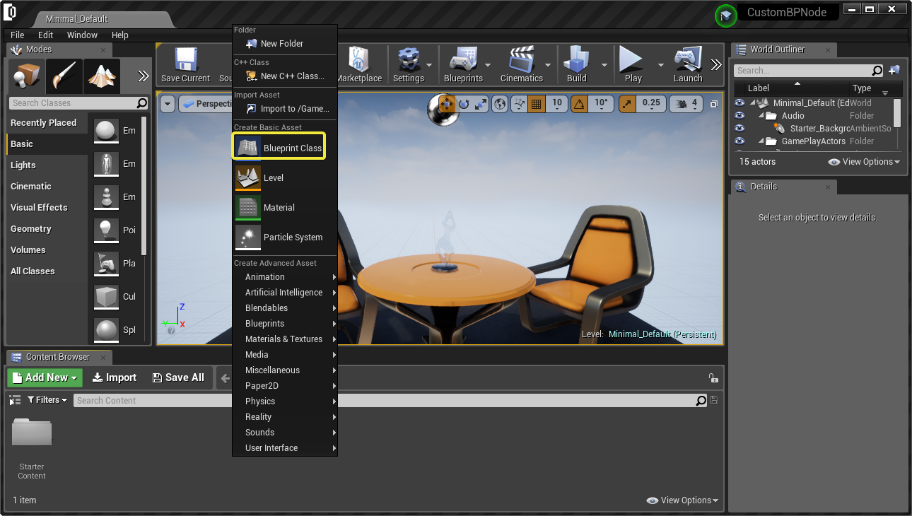
Start Reality Editor, right click on the Content Browser and select BLUEPRINT CLASS
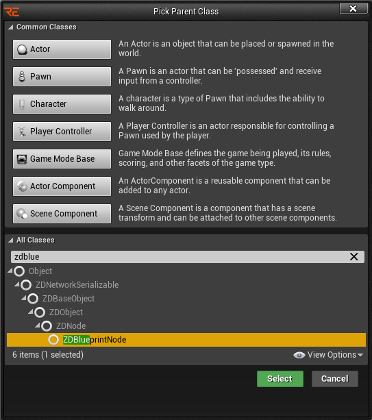
Select ZD BLUEPRINT NODE from the All Classes section
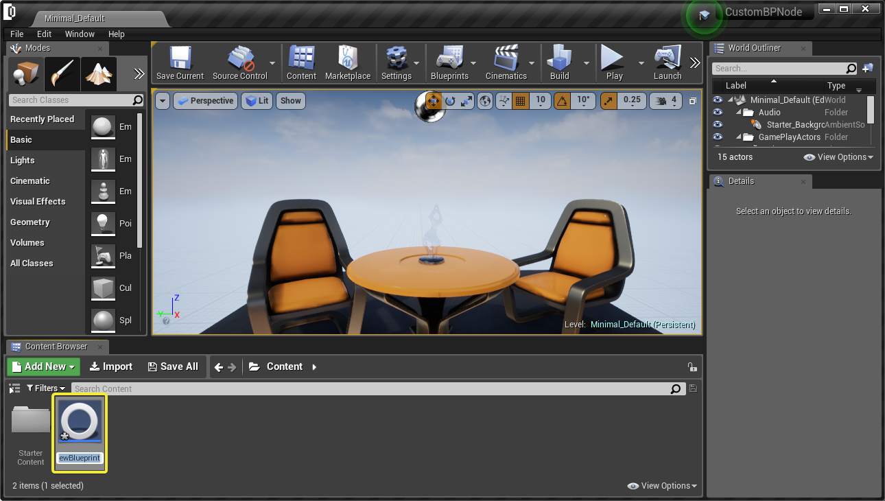
You will see the new BluePrint on your Content Browser, click to rename it, here in this example the name would be "NewZDNode".
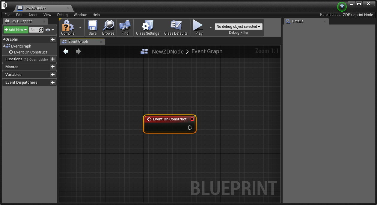
And then double click on this node to open Blueprint Editor and click ADD NEW and then go to OVERRIDE FUNCTION and ON CONSTRUCT
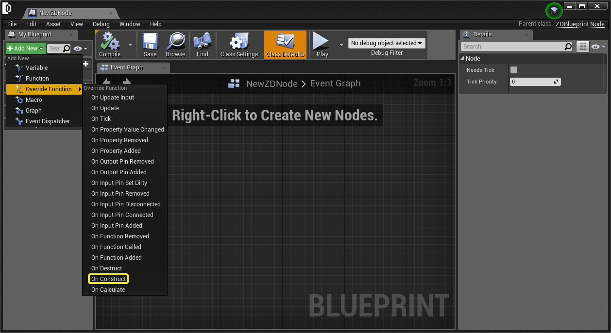
You will see that EVENT ON CONSTRUCT will be added to the Event Graph of this Blueprint
Adding Input and Output Pins
Reality Editor accepts various types of input and output pins. Right click on Event Graph and search for Input Pin to add an input pin.
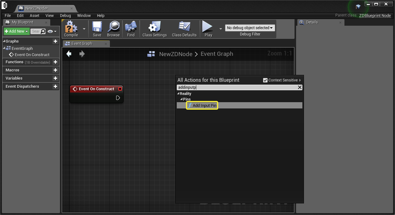
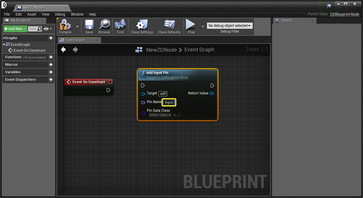
Rename the pin by clicking the box on the right of PIN NAME and write “Input” or any other pin names you would like to use.
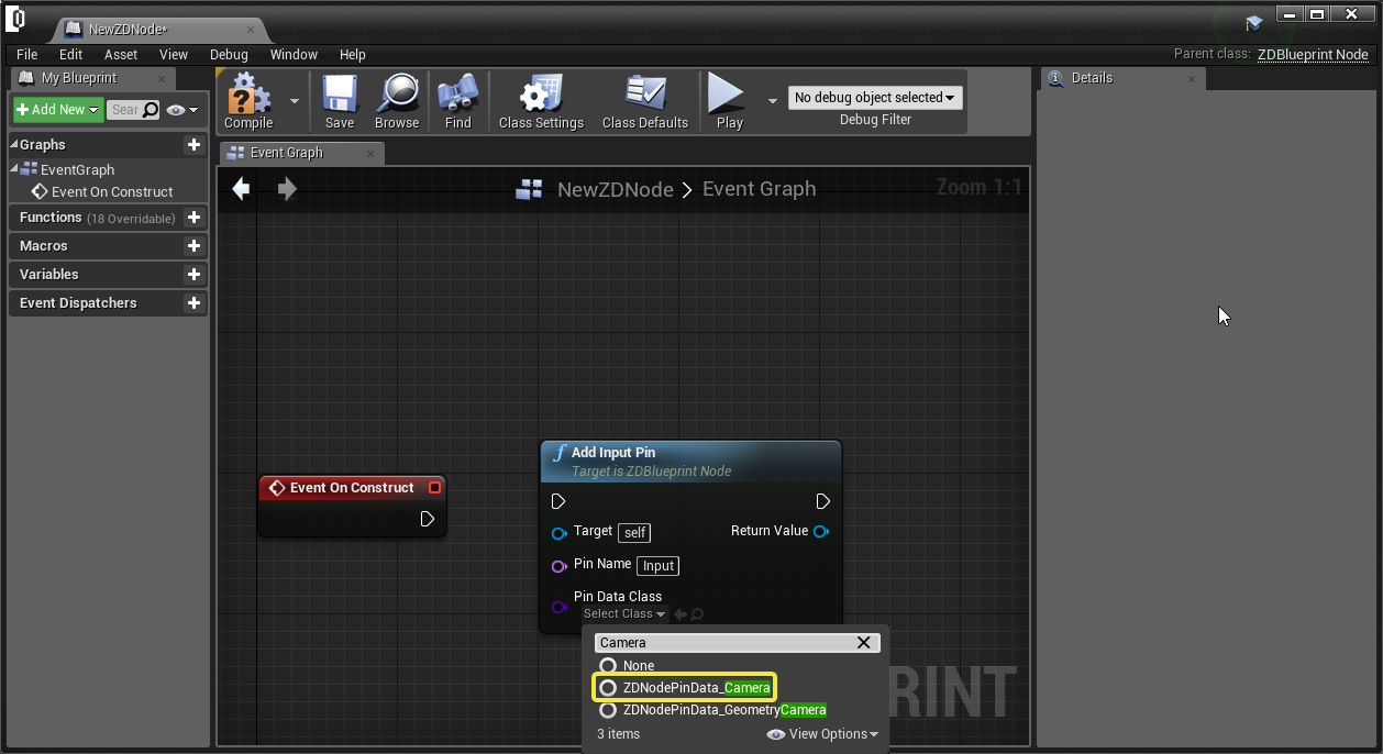
Now choose the PIN DATA CLASS as “ZDNodePinData_Camera” or any type of input that are available on Reality Suite.
Input pin is added successfully. Now add an OUTPUT PIN by right-clicking the event graph and select “Add Output Pin”
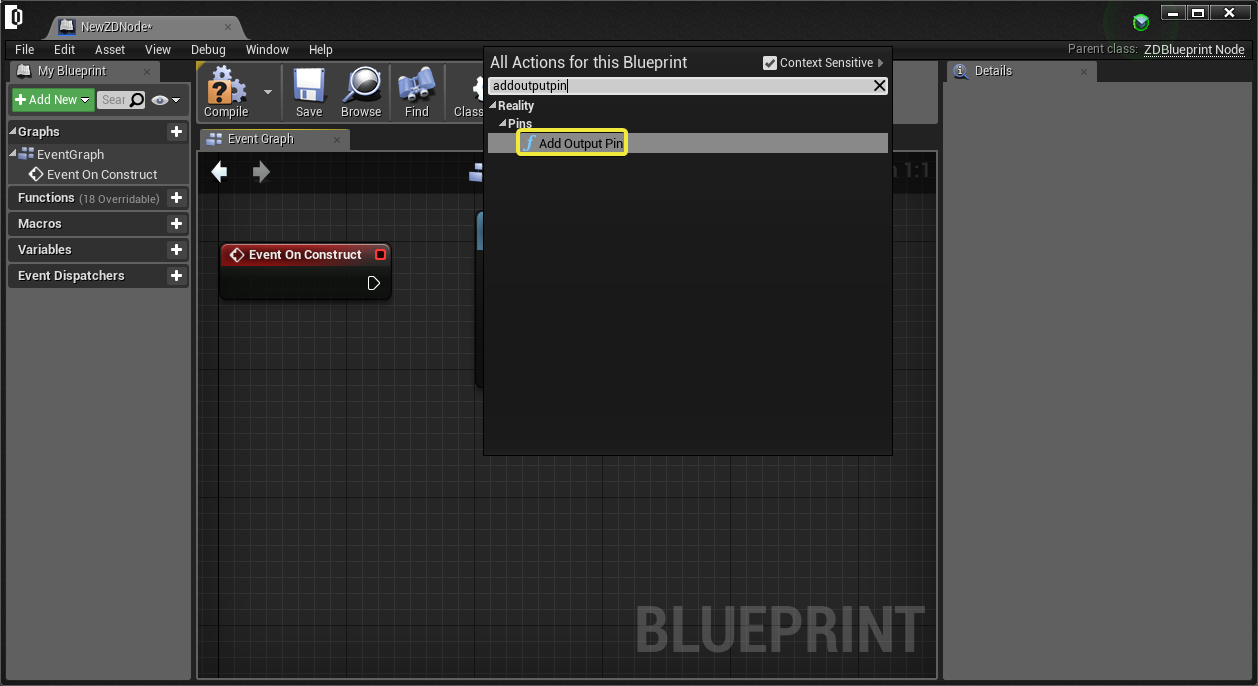
Change PIN NAME to “Output” and PIN DATA CLASS to “ZDNode Pin Data”.
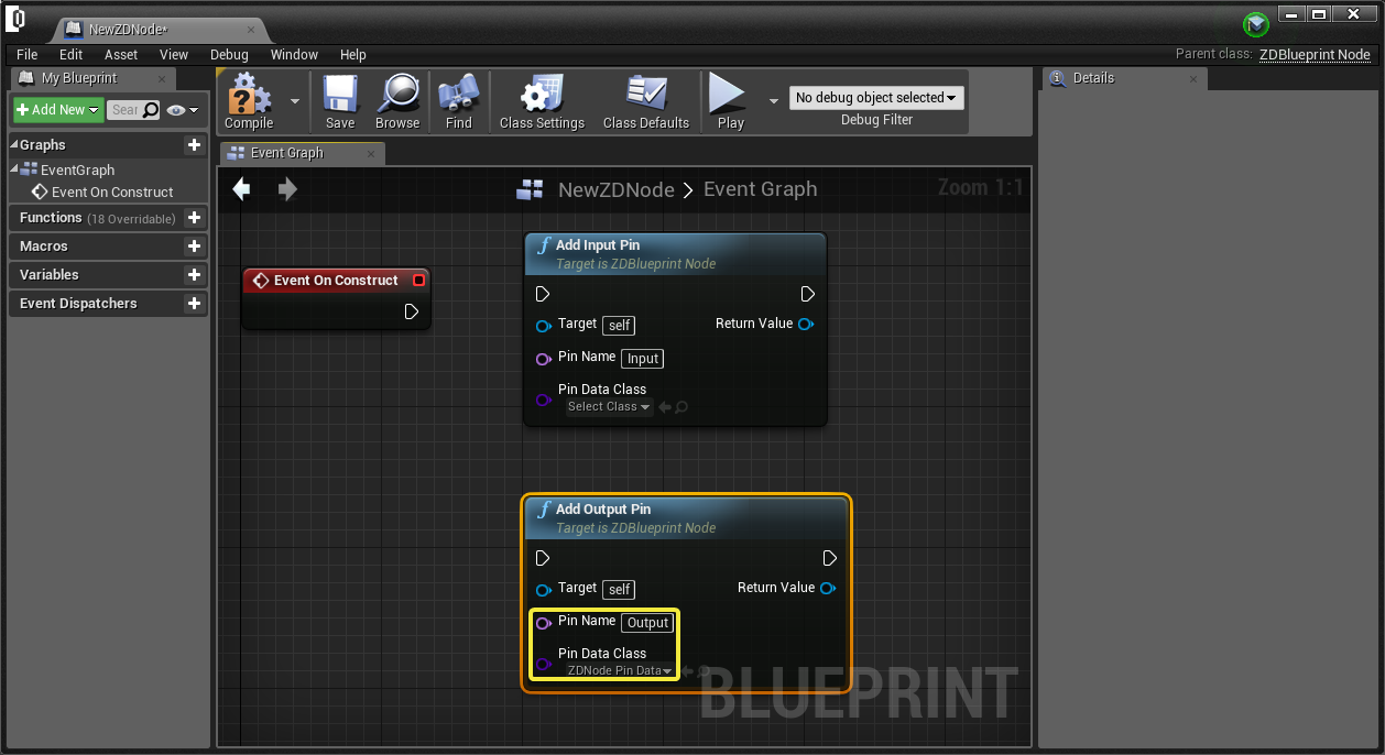
Connect EVENT ON CONSTRUCT to ADD INPUT PIN and then connect ADD INPUT PIN to ADD INPUT PIN as shown below. This pipeline will create both input pin and output pin at the construction of the pin.
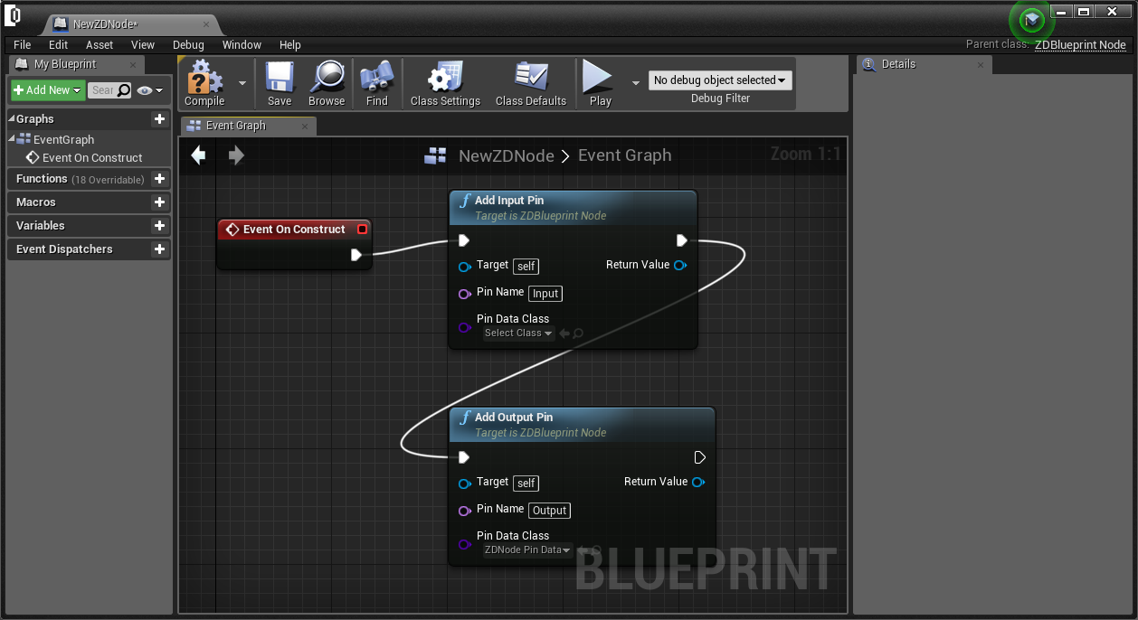
Press SAVE and COMPILE to save and compile the changes on this custom node.

Exporting to Reality Setup
Once the custom node is created, it has to be exported to Reality Suite. For this, Go to EDIT and PROJECT SETTINGS on Reality Editor.
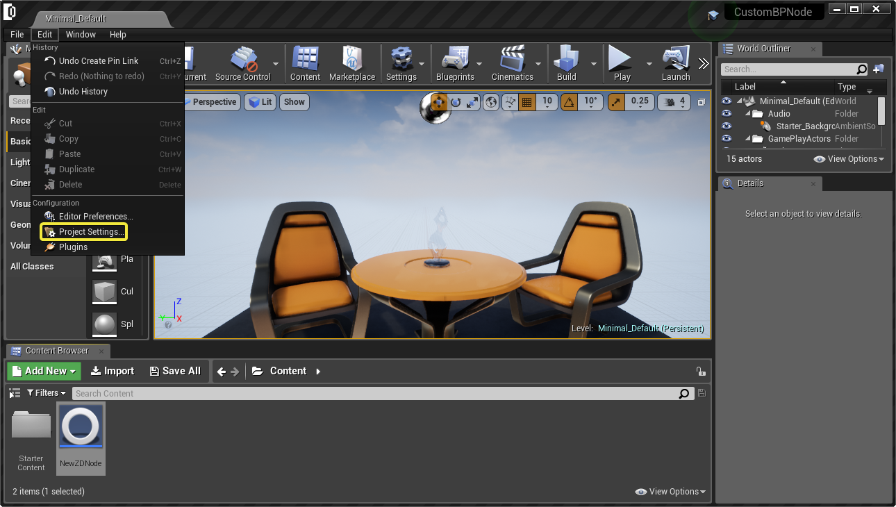
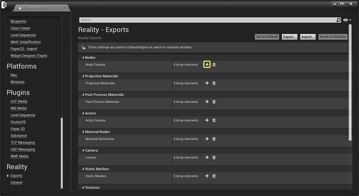
Go to REALITY - EXPORTS on the left menu and add a Node Class by clicking ➕ icon
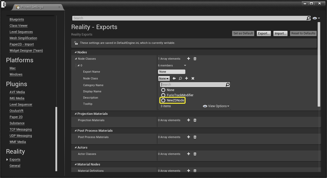
Choose Node Class as “NewZDNode” which you already created as a Blueprint and listed here:
Write a suitable “Export Name” which will appear in the Node Graph in Reality Setup and add a Category Name which will be shown as one of the categories such as Tracking, UE Render etc... Here in this example write “New Node Category”.
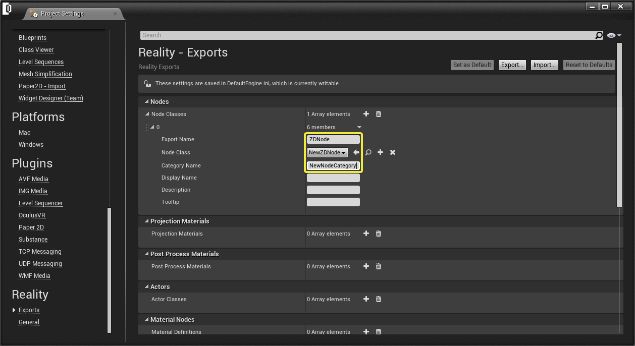
You can close this window safely as these settings are already saved. Your node is created and exported as a node successfully.
Adding Properties
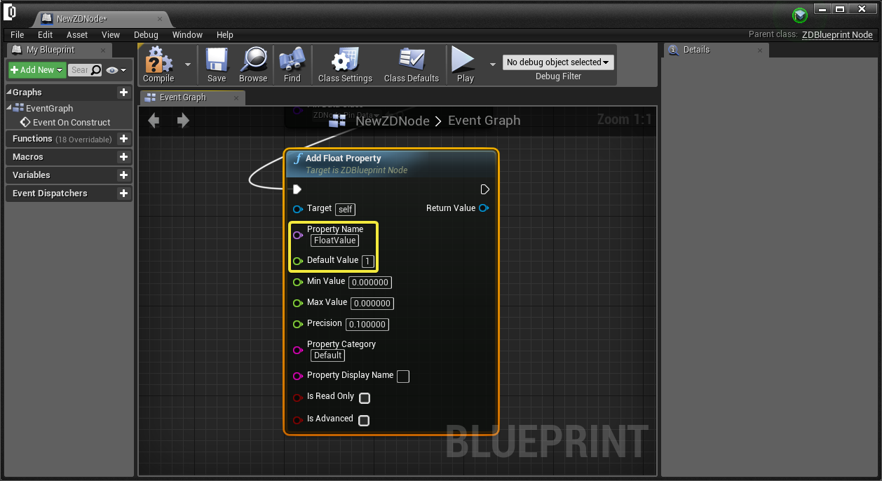
To add a property for the node, again right click on the Blueprint Event Graph and select “Add Float Property”, you can choose various properties to add to your pin.
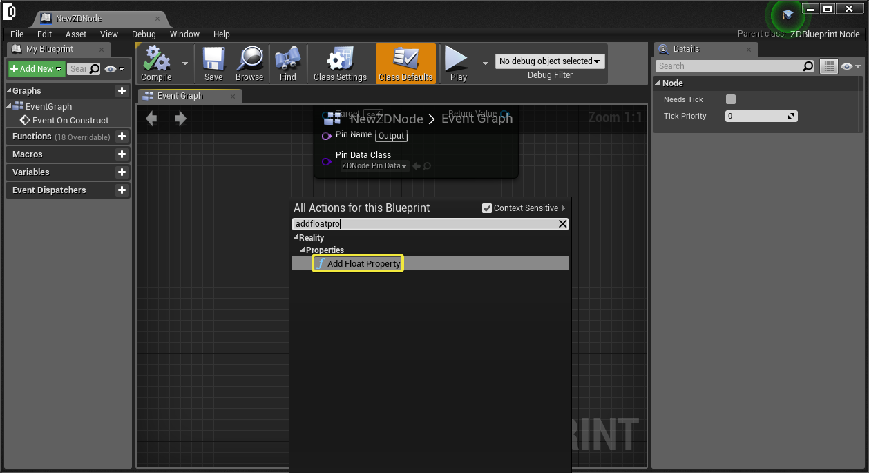
After adding property, you can change Property Name as “FloatValue” like this tutorial and Default Value to “1” or any other value is possible. Connect it to “Add Output Pin”. And then compile and save to add this property to your node.
Using in Reality Setup
Click on Play button in the Editor. Then click on UNKNOWN ATTACHMENT icon on the desktop to start Reality Setup Application. Right click on the nodegraph and go to zdCreate > New Node Category > ZDNode to add ZDNode to your nodegraph.
See the properties on the right of Reality Setup and note that the property and the default value is added successfully.
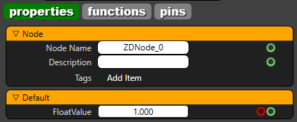
As like this example, you can create customized nodes, with custom I/O values, with various types depending on your needs.
A Custom ZDBlueprint Node Example: Negate Node
Exporting an existing Blueprint Node
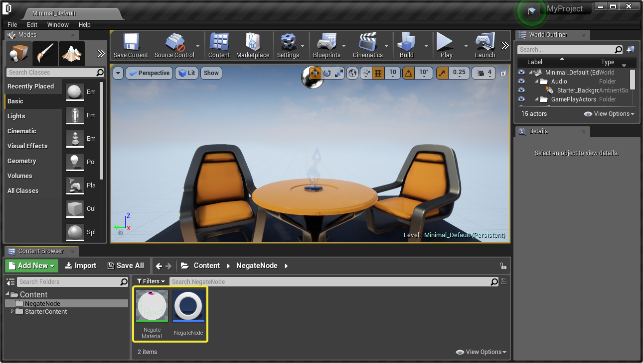
To be able to use your custom Blueprint Nodes, you have to copy them to the Content folder of the project.

After putting the node folder in the projects Content folder, relaunch the project on Reality Editor and notice that the node is accessible on Content Browser of Reality Editor.
Opening Blueprint Editor
Double click on Negate Node to open the Blueprint Editor and see the pipeline.
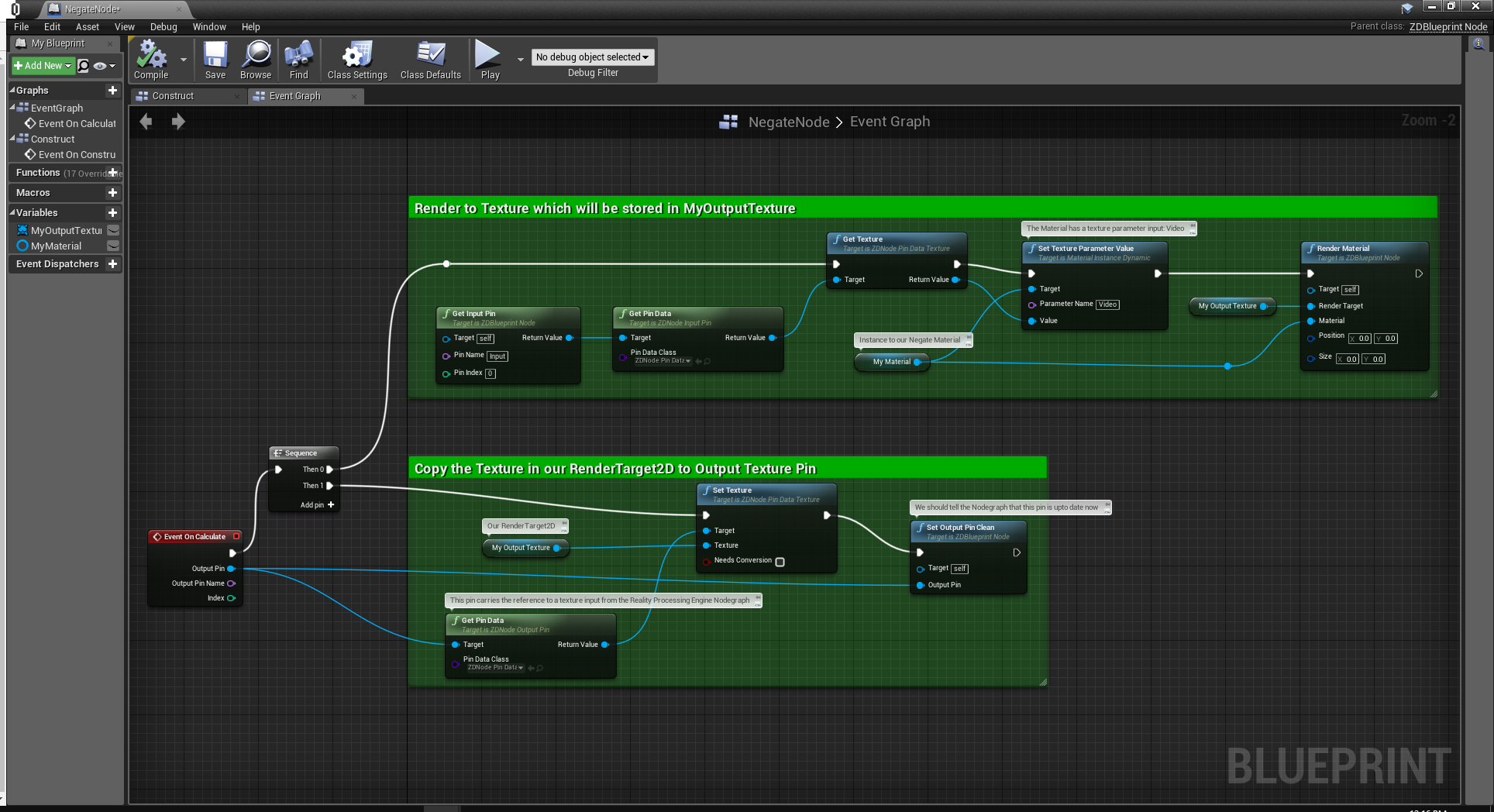
The menu on the left shows the Graphs, Functions, Macros, Variables and Event Dispatchers of the Blueprint Node.
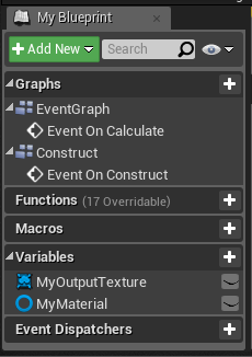
- Graphs: Event graphs are used to create and edit pipelines for the functioning of the node, such as Event On Calculate etc.
- Functions: Group of functions that are used on event pipelines.
- Macros: Group of macros that are used on event pipelines.
- Variables: Group of variables that are called on events. In this example, there are two variables as MyMaterial and MyOutputTexture thar are used on Event On Calculate.
- Event Dispatchers: Event dispatchers broadcasts/calls an event to the other eventgraphs.
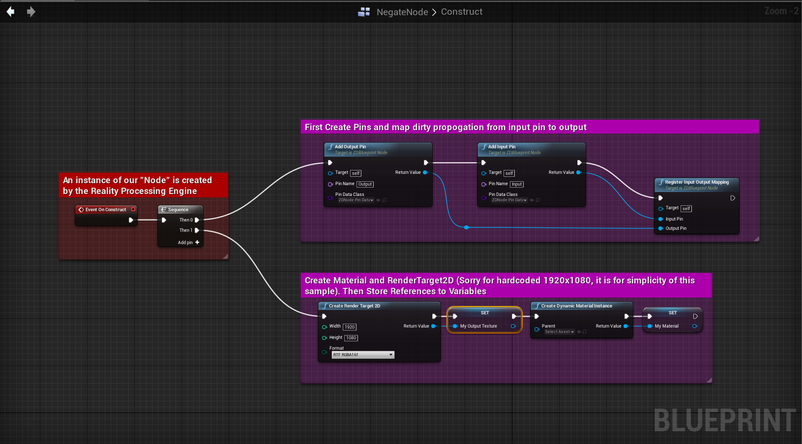
In this example, there are two event graphs:
- Event On Construct: This graph is created for creating the pins, properties and default values of the pins and properties of the node.
- Event on Calculate: This graph shows the events that are called when the value of the pins and/or properties change on the node.
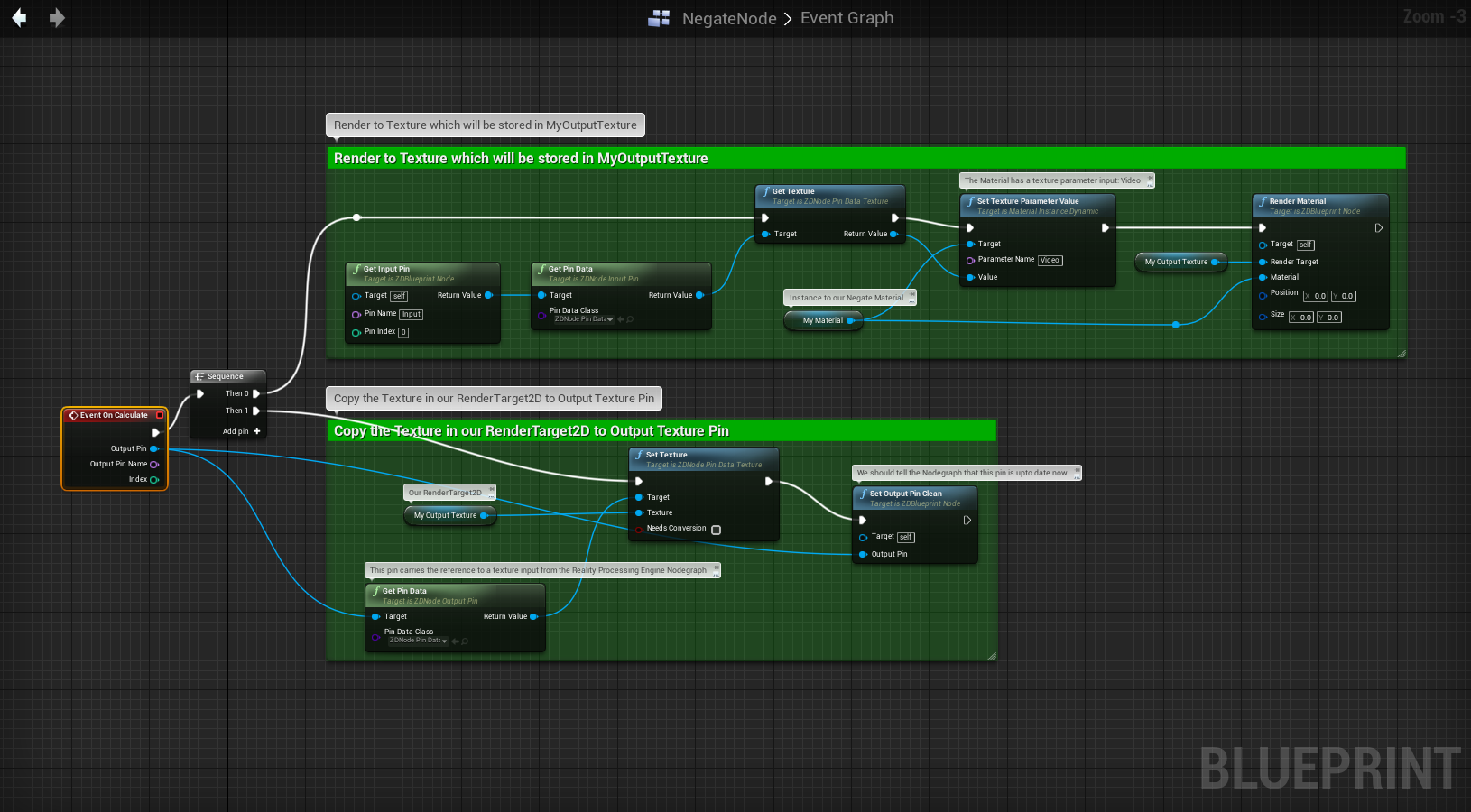
If you make any changes, just press COMPILE and SAVE buttons and close the Blueprint Editor. Export this Node through the REALITY EXPORTS menu on PROJECT SETTINGS as shown above and start using in your Reality Setup Nodegraph.